
Loop Analysis
Summary:
Different methods are used to analyze and solve circuit problems in the provided circuit diagrams and examples. In the first example, Kirchhoff’s Voltage Law (KVL) is applied to determine the voltage and current in a circuit with seven branches and six nodes. KVL equations are formulated for two loops, I1 and I2. These equations are solved by substituting values for resistances and voltages. The solution shows that I1 and I2 are equal to 0.69 and 0.0869, respectively. In the second example, the circuit has one current source and one voltage source. It is found that I1 is constrained to be 1 A, and I2 is calculated to be 402 mA. In the next example with a dependent voltage source, the loop currents are given in Figure 3. The equations are combined to produce a matrix form, which is then solved for Inverse to find I1 and I2, yielding I1 = 1.5 mA and I2 = 1.5 mA. In the final example, three linearly independent equations are derived based on circuit analysis. The KVL equation for the last loop is solved to find I3, which results in IO = -4/3 mA. The super mesh technique is introduced to avoid introducing the unknown voltage Vx. The KVL equation is written around the dotted path, defining the super mesh using the original mesh currents. This approach yields the desired result without needing to consider Vx.
Excerpt:
Loop Analysis
How to determine equation;
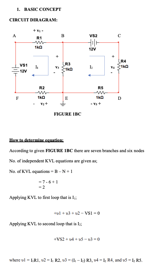
According to given FIGURE 1BC, there are seven branches and six nodes
No. of independent KVL equations are given as;
No. of KVL equations = B – N + 1
= 7 – 6 + 1
= 2
Applying KVL to the first loop, that is, I1;
+υ1 + υ3 + υ2 − VS1 = 0
Applying KVL to the second loop that is I2;
+VS2 + υ4 + υ5 − υ3 = 0
where υ1 = I1R1, υ2 = I1 R2, υ3 = (I1 – I2) R3, υ4 = I2 R4, and υ5 = I2 R5.
Reviews